
Measurement of Peeling Defect of Zirconium Coating Materials
When a test piece is heated, the surface temperature distribution represents nonuniform result with reflecting the defects within the test piece. With observing nonuniform result, Defect Detection by Thermography helps to identify the presence of defects, their locations and shapes in non-destructive manner which uses Infrared Thermography. The objective of this experiment is to evaluate the intactness of heat insulating Zirconium coating material, which is used to improve the durability of high temperature gas supplying tubes in the gas turbine of Thermal Power Plant.
Detectability of Peeling Defect with Model Test Piece
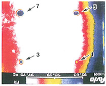
Model test piece A (Fig.2) was observed by an experimental equipment to detect peeling defect (Fig.1). Test piece has been heated on the hot plate until its surface temperature reaches about 1OO℃, and cooled down by natural cooling. Photo 1 shows a thermal image of the test piece right after above processes finished. As a result of this experiment, peeling defect of 1mm in diam was detected, and the data for ΔT were obtained to be 3 - 4℃ for the defect size of 5mm in diam.

- Fig.1: Outline of Test Equipment
- Fig.2: Model Test Piece A
Effect of Thickness Variation of Coating Layer
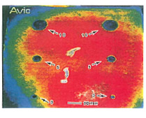
The model test piece B, which has thickness variation defect in coating layer, was fabricated and tested to observe changes. (Thickness variation is 180-700µm, the defect sizes are 3, 5 and 10mm diam.) Since easy heating and cooling are required for actual material, heating was done by Infrared Lamp radiating coating layer to heat up to about 1OO℃, cooling was by natural cooling with the room temperature of 22 - 24℃. Figure 2 shows a part of cross section of coating layer of test piece with the thickness of about 690µm, and Figure 3 shows thermal image of it. The result is that, as the thickness of coating layer increase, Δ T also increases and the rate of change is about 0.14℃/1Oµm.
Future Investigation
In order to improve the detectability of peeling defect in actual materials, uniform heating and cooling method and advanced thermal image data processing method have to be investigated.
-
Photo 1: Thermal image 01 Test Piece
(by TVS-210) 
- Photo 2: Cross section 01 Test Piece B
-
Photo 3: Thermal image 01 Test Piece B
(by TVS.B200)
- *Information was provided by Fine-ceramic-center.